Evolution of Circuitry Technologies
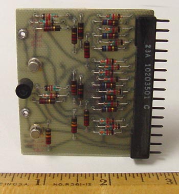
| This is an early module developed by CDC prior to the advent of the 6000 series. It was used in some of the earlier machines such as the 1604 and 3000 series.
To the right in this picture are the pins used to plug it into the backplane. This board contains two transistors (the small aluminum-colored cans a little way in from the left edge) and essentially implememts a single flip-flop that can register and hold one bit. The large black cylinder in the middle of the left edge is not an electronic component - it is merely a spacer to keep separation between multiple boards when they are all plugged into the backplane side-by-side. The two holes on the left edge with silver-colored grommets are points to which test-probes can be attached. |
|
| Here we see a much greater packing density where two circuit-boards are mounted in one pluggable module, with their component surfaces facing inward toward each other. The pins used to plug it into the backplane are on the left, and contacts for test probes are mounted on the right. | 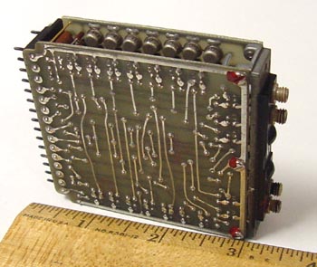
|
| This is the same module viewed end-on. Here we see a bunch of transistors mounted on each board, with some components such as resistors and diodes mounted in between, with one end connected to each board. This configuration gave rise to the name "cord-wood packaging". This type of dense packaging however gave rise to cooling problems in that it was too restrictive to support sufficient cooling by the traditional method of forced cold air flow over the components. Instead, cooling was achieved by cold bar conduction: the cordwood modules were inserted and screwed in place in compartments and the two large flat surfaces were in contact with aluminum sheets which conducted the heat to the horizontal members of the frame, which in turn contained circulating Freon. (Thanks to Peter Capek for pointing out a clarification here) | 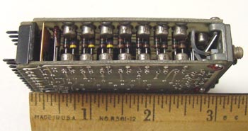
|
| This is a later module where we see the transition from discrete technology (using individual
components such as transistors, resistors, diodes, etc.) to the use of integrated circuits in chips. The chips
are again mounted on two inward-facing boards to make a module. This transition only occurred once integrated
chip circuitry was available that could match the speed of the earlier discrete circuitry.
However, this density came at an even greater cost in heat dissipation problems. You can see a silver-colored plate (resembling four fence-posts in a gate) mounted on the outer surface of each board by means of four clips. This was to draw heat from the chips and provide a more efficient conductive path to the cooling elements. The holes on the right are the test-probe connections. | 
|
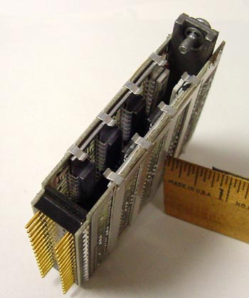
| This is the same module, showing how the chips are mounted inside. Note how each
"fence post" on the outer cooling plate aligns with the bellies of a row of chips in an attempt to
suck out the heat and conduct it to the cooling elements.
Also of note is that this module no longer relies on its connector pins to hold it into the chassis. There are two screws on the end-plate which are used to firmly bolt it into place - partly to protect against any vibration that might compromise electrical integrity, and partly to assure good mechanical contact for heat dissipation purposes. |
|