Early Memory Technology
| On this page we look at the core memory in greater detail - using the screen width to show greater resolution images |
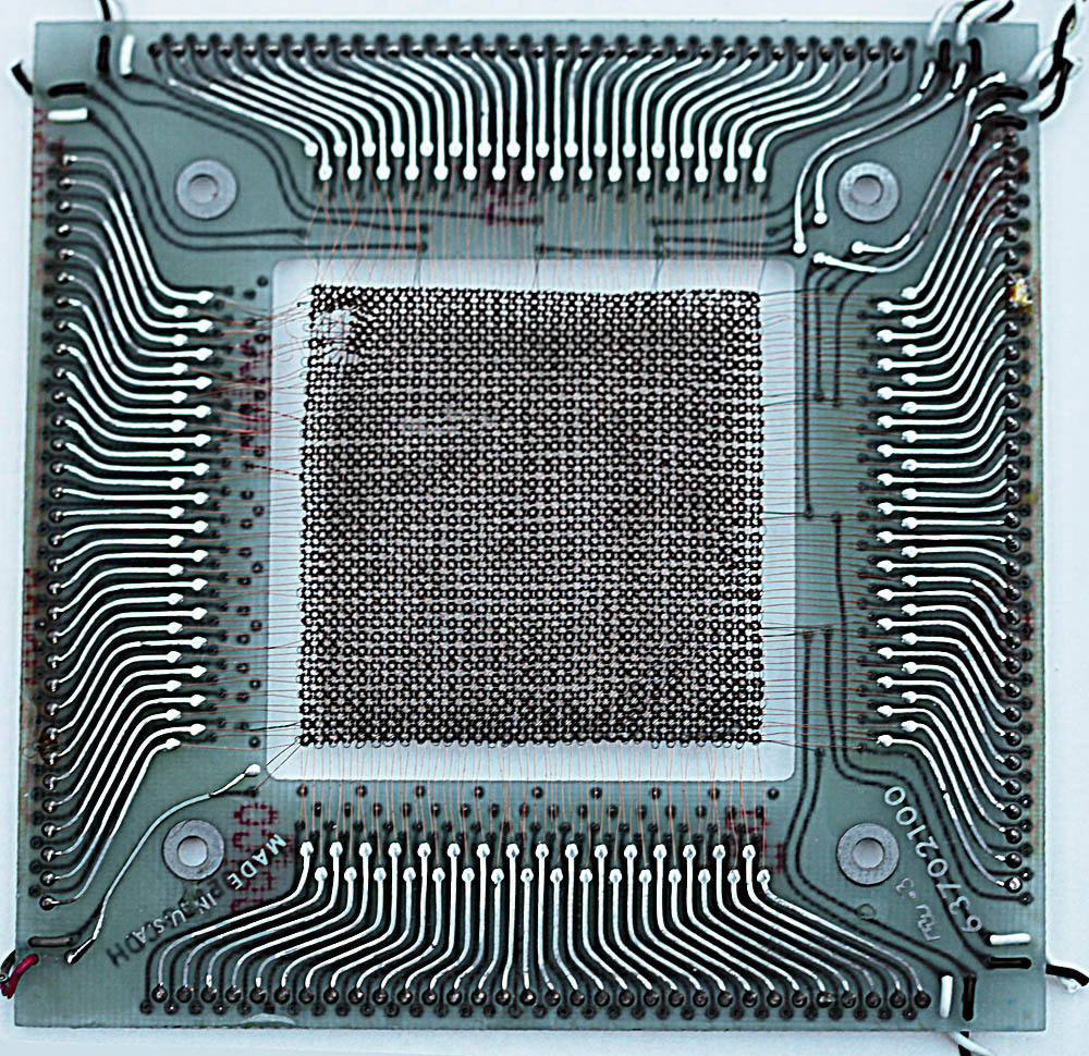
| Here we see one complete memory plane - note the obvious mechanical damage to the core plane near the top left corner (some clumsy oaf with a screwdriver probably) - and if you look closely there is another anomaly just below and to the right of this damage. If you can't see it in this image, it will be made clearer in the next image. |
 |
|
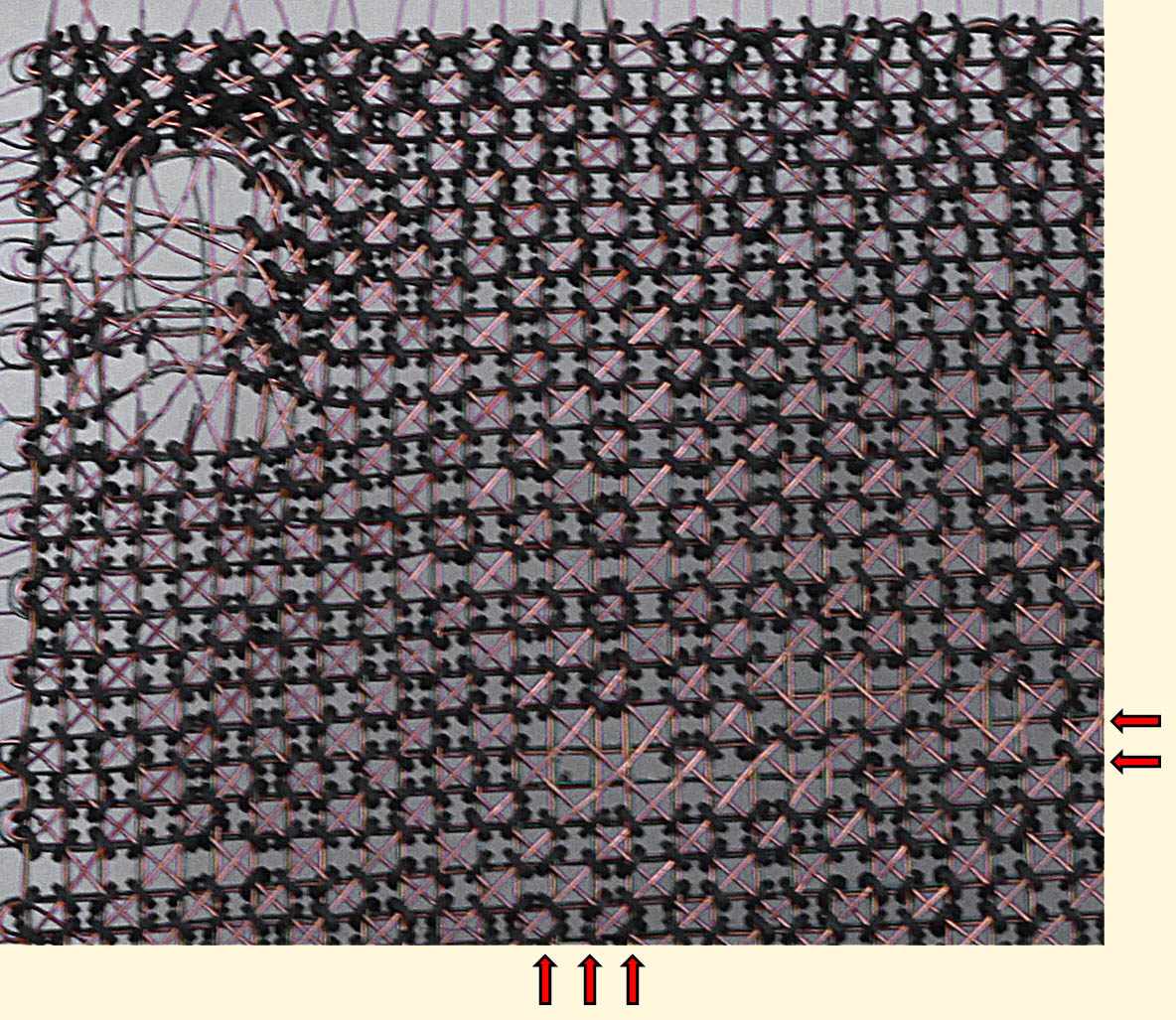
Following is a macro photo of the top left corner of the plane. The mechanical damage in the top left corner is obvious - the wires have been forcibly distorted and cores are missing.
If you look at the intersection of the arrows (below and to the right of the image) you will see an anomaly that I'm not sure I can explain. Clearly some cores are missing - but there appears to be no evidence of forcible damage. Was this a manufacturing fault? Did all core planes have some "missing bits" - perhaps compensated for with a flaw map pointing to substitute "bits" on a "spare" core plane? (While such a technique was used on some disk drives where one surface was used as a "spare" to accomodate an alternate home for "flawed sectors", I don't think this was likely with core memory as such a table would use up quite a chunk of already scarce and very expensive memory) |
 |
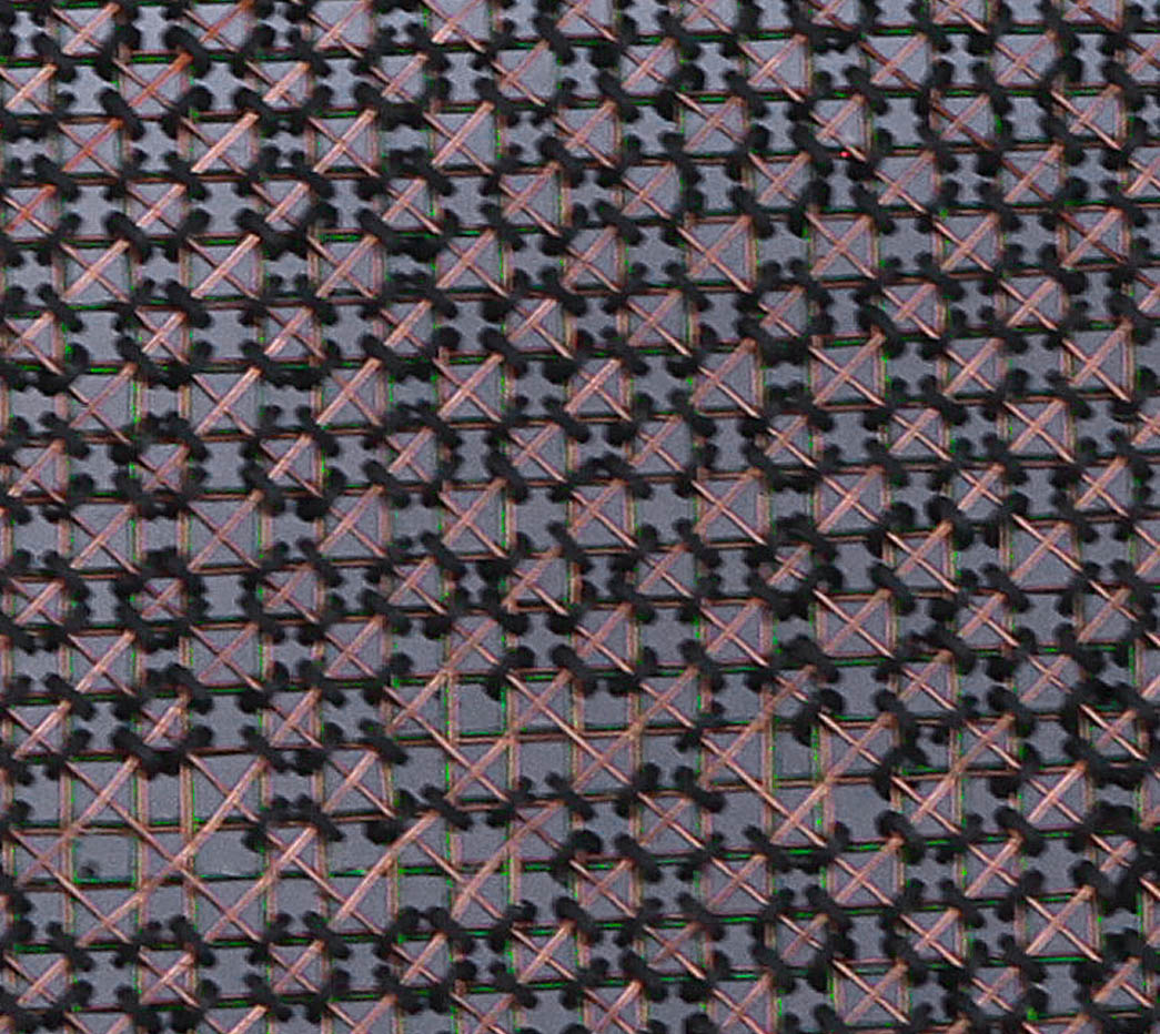
This is an even more detailed look at a small section. At first glance it would appear that there are four wires as follows:
Looking even more carefully, we can see that each doughnut is also threaded by a horizontal and a vertical.... BUT each horizontal and vertical is actually a pair of wires, one copper-colored, the other green. Thus each core is threaded by 5 wires, - two horizontal, two vertical, and a diagonal. (In some spots on the photograph it might appear that the diagonal heading North-East is also double, but I think this is more an artefact of the resolving power of the camera lens - especially since we know that the North-East diagonal and the North-West diagonal are in fact the same wire threaded back-and-forth across the plane in criss-cross fashion.. |
 |
|
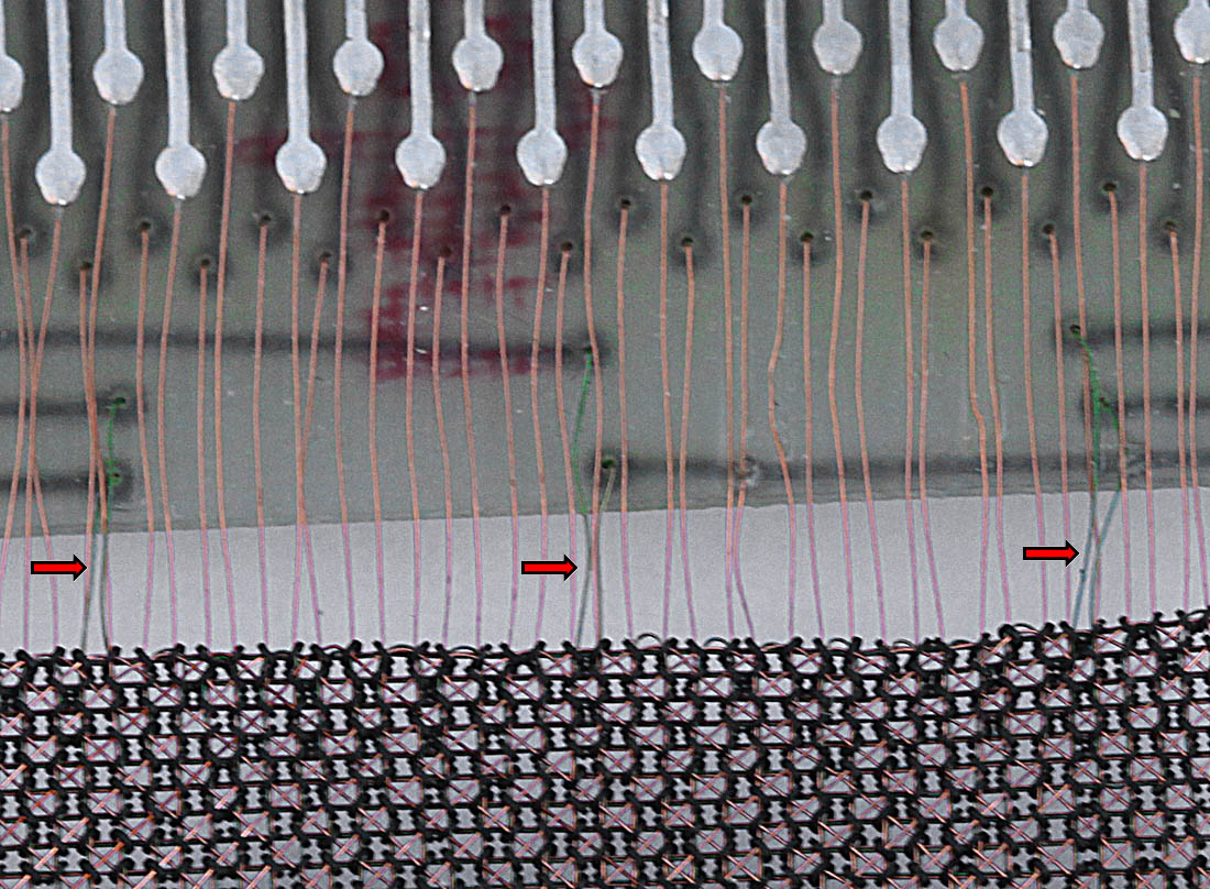
The following image shows clearly that when a diagonal wire reaches the edge it merely turns 90° and becomes the "opposite" diagonal, i.e. a North-East turns right
and heads South-East - effectively a North-West diagonal in terms of the terminology we used above.
Also we can see that the green wires (see red arrows on image) are separate conductors with their own connections to the outside world (as opposed to a mere doubling-up to make a two-threaded conductor for mechanical strength.) These green wires are the "inhibit" wires. One can see at the edge connectors that there is one green wire for every 16 copper-colored wires. That tallies with the documentation: there are four horizontal inhibit wires (each covering a quarter of the memory plane) and ditto for the vertical. Thus for example, when writing into address 0, the inhibits for group X=0..15 and Y=0..15 are activated. A correspondent (Paul Koning) surmises that this might have been done to provide a closer inductance match between the x/y address lines and the inhibit lines, thus allowing the use of the same (type of) current amplifiers to deliver the signals as well as keeping the pulses short. This was probably necessary given the state of memory technology in 1964 when this design was pushing the state of the art. Obviously all the conductors in the matrix must have some kind of insulated coating, otherwise there would be rampant shorting between x, y, sense and inhibit. |
 |